
This guide provides step-by-step instructions on using the Optical Power Meter (OPM VFL 50) to measure optical power, detect fiber faults with VFL, and check RJ45 cable wiring for optimal network performance.
Knowledge Base:
Practical Implementation of Optical Power
Meter (OPM VFL 50)
Introduction
This
knowledge base provides a step-by-step guide on the practical implementation of
the Optical Power Meter (OPM VFL 50). This device integrates OPM, Visual Fault
Locator (VFL), and RJ45 cable color grading functions, making it a versatile
tool for fiber optic and networking applications.
Practical
Implementation of OPM VFL 50
ü Powering On the Device
ü Press the power button to turn on the OPM VFL 50.
ü Ensure the display is clear and functional.
ü Select the appropriate mode (OPM, VFL, or RJ45 color grading
check).
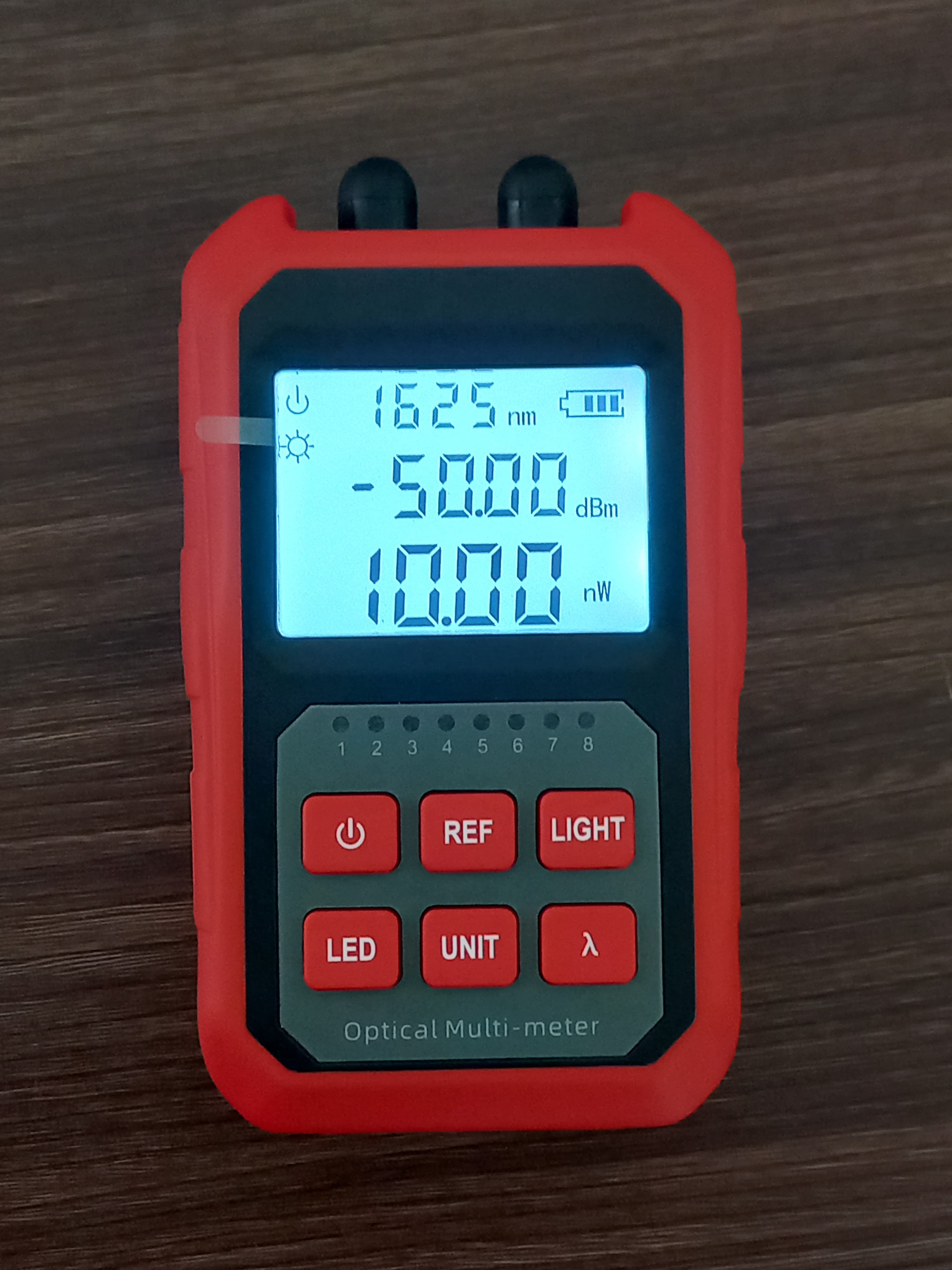
Ø Using the Optical Power Meter (OPM) Function
Measuring Optical Power
1.
Connect the fiber optic cable to the
OPM port.
2.
Select the correct wavelength (e.g.,
1310nm, 1550nm, or 1625nm).
3.
Observe the power level displayed in
dBm.
4.
Compare the reading with acceptable
loss levels for network performance.
5.
If power levels are too low, check
for cable issues or signal loss.
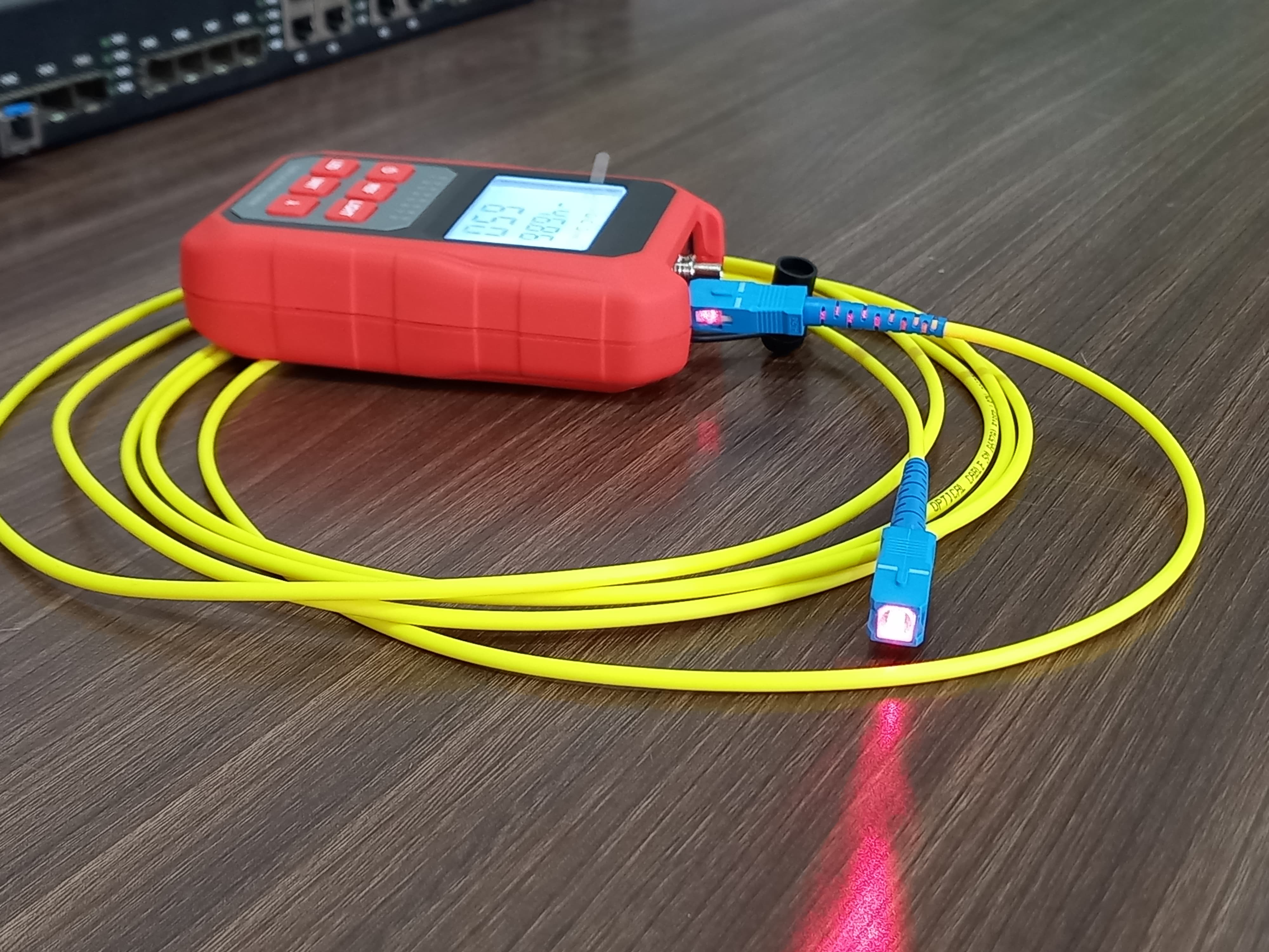
Ø Using the Visual Fault Locator (VFL) Function
Detecting Faults in Fiber Cables
1.
Connect the fiber optic cable to the
VFL port.
2.
Turn on the VFL to emit a red laser
light.
3.
Inspect the fiber cable for visible
red light leakage.
4.
Identify breaks, bends, or
misalignments in the fiber.
5.
If faults are found, mark the
affected area for repairs or splicing.
Ø Checking RJ45 Cable
Color Grading
Verifying RJ45 Cable Wiring
1.
Strip the outer sheath of the
Ethernet cable carefully.
2.
Arrange the internal wires according
to T568A or T568B standards.
3.
Insert the wires into the RJ45
connector in the correct order.
4.
Use the OPM VFL 50 tester function
to verify correct wiring.
5.
Insert one end of the RJ45 cable
into one connector and the other end into the additional connector.
6.
Observe the emitted light sequence:
§ The lights will emit turn-wise, indicating the connectivity
of each wire.
§ If a light does not turn on, check for incorrect wiring or
faulty connections.
7.
Ensure that the corresponding lights
on both connectors turn on in sequence.
§ If any light does not match, verify the pin alignment and
crimping.
8.
If miswiring is detected, reassemble
and test again.
Conclusion
The Optical
Power Meter (OPM VFL 50) is a multifunctional tool that simplifies fiber optic
and network cable tasks. By following these steps, technicians can
efficiently measure optical power, detect fiber faults, and verify RJ45 cable
wiring, ensuring optimal network performance and reliability.
.jpeg)

Our Partners


Secure Payment By