
10G SFP+ 1310nm Dual LC
10KM
Brand:
D-TECH
Variant Specifications
Warranty:
Weight:
Country of Origin:
More Details:
Import Lead Time:
Package:
1% OFF
Rs 2,467.90
List: Rs 2,497.50
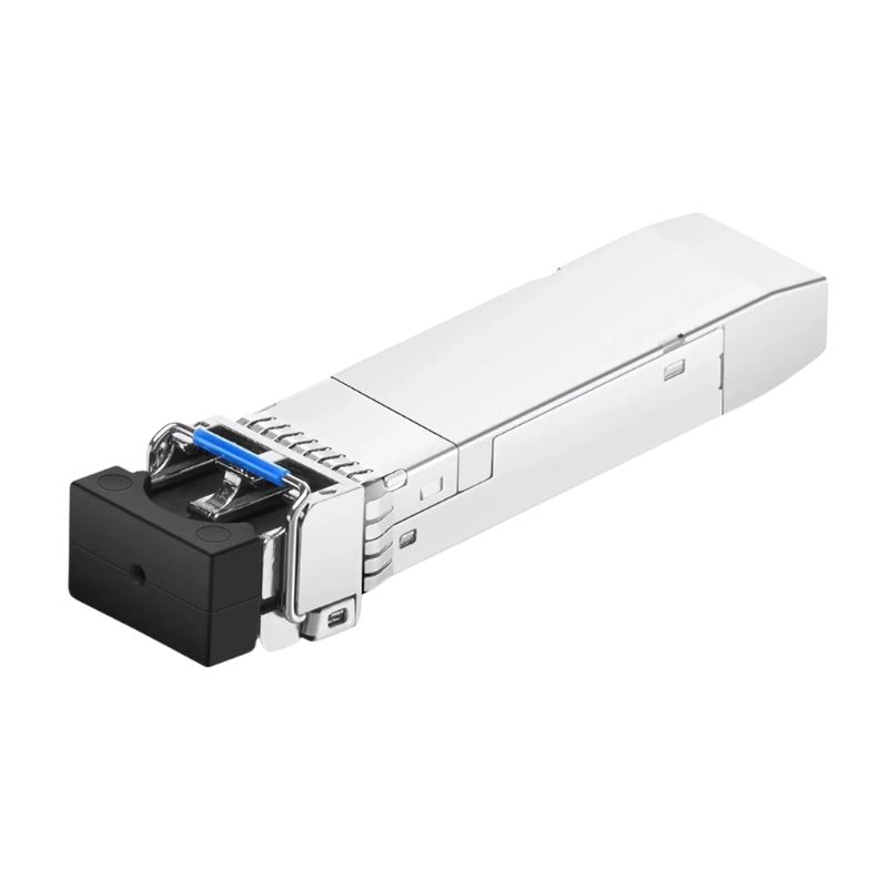
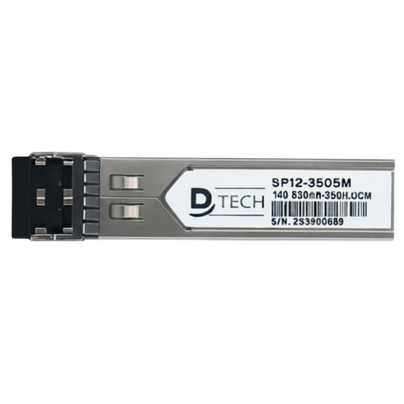
10G SFP+ 1310nm Duplex LC Transceiver (DT10G) -10km
The DT10G 10G SFP+ optical transceiver is designed for high-speed data transmission over single-mode fiber. It supports up to 60 km transmission distance, making it ideal for data centers, ISP backbone networks, and long-distance enterprise connectivity. With low power consumption and full digital diagnostics monitoring, it ensures stable and efficient network performance.
Key Features
| 10G high-speed transmission up to 10.3125 Gbps |
| 1310 nm wavelength for long-distance single-mode fiber links |
| Supports transmission distance up to 60 km |
| DFB laser transmitter with high stability and performance |
| DDM/DOM supported for real-time monitoring |
| Hot-pluggable SFP+ form factor for easy installation |
| Low power consumption and strong EMI protection |
Technical Specification
| Category | Specification |
|---|---|
| Model | DT10G |
| Product Type | 10G SFP+ Optical Transceiver |
| Application | 10G Ethernet, Data Center, ISP Networks |
| Form Factor | SFP+ (Hot-pluggable) |
| Data Rate | 10.3125 Gbps |
| Wavelength | 1310 nm |
| Transmission Distance | Up to 60 km |
| Fiber Type | Single Mode Fiber (9/125 µm) |
| Connector Type | Duplex LC |
| Optical Interface | Duplex LC/UPC |
| Transmitter Type | 1310 nm DFB Laser |
| Receiver Type | PIN + Preamplifier |
| Transmit Power | -6 to -0.5 dBm |
| Receiver Sensitivity | ≤ -14.4 dBm |
| Overload Power | ≤ 0.5 dBm |
| Extinction Ratio | ≥ 3.5 dB |
| Spectral Width | ≤ 1 nm |
| SMSR | ≥ 30 dB |
| Power Supply | +3.3 V |
| Power Consumption | ≤ 1.2 W |
| Supply Current | ≤ 360 mA |
| DDM / DOM | Supported (SFF-8472) |
| Monitoring | Temperature, Voltage, TX/RX Power, Bias Current |
| Compliance | SFP+ MSA, SFF-8472, IEEE 802.3ae |
| EMI Protection | Metal Housing |
| Operating Temperature | 0°C to +70°C (Commercial) |
| Extended Temperature | -10°C to +80°C |
| Industrial Temperature | -40°C to +85°C |
| Storage Temperature | -40°C to +85°C |
| Humidity | 5% – 95% (Non-condensing) |
Ask a question
Questions & answers
0 question(s)No questions yet. Be the first to ask!
0.0
5★
0
4★
0
3★
0
2★
0
1★
0
Write a review
Sign in to reviewCustomer reviews
No reviews yet. Be the first to review this product.
No videos for this product yet
Once videos are added, you’ll see them here as a gallery.
Related Products
XGSPON OLT STICK
Contact for price
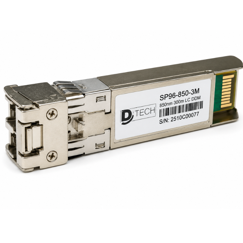
Multimode SFP 10G SR 850nm
Rs 2,987
Rs 2,965
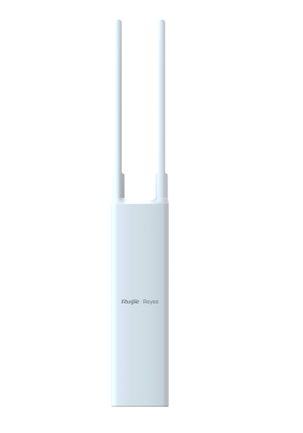
Wi-Fi 5 AC1300 Dual-Band Outdoor Access Point
Rs 20,240
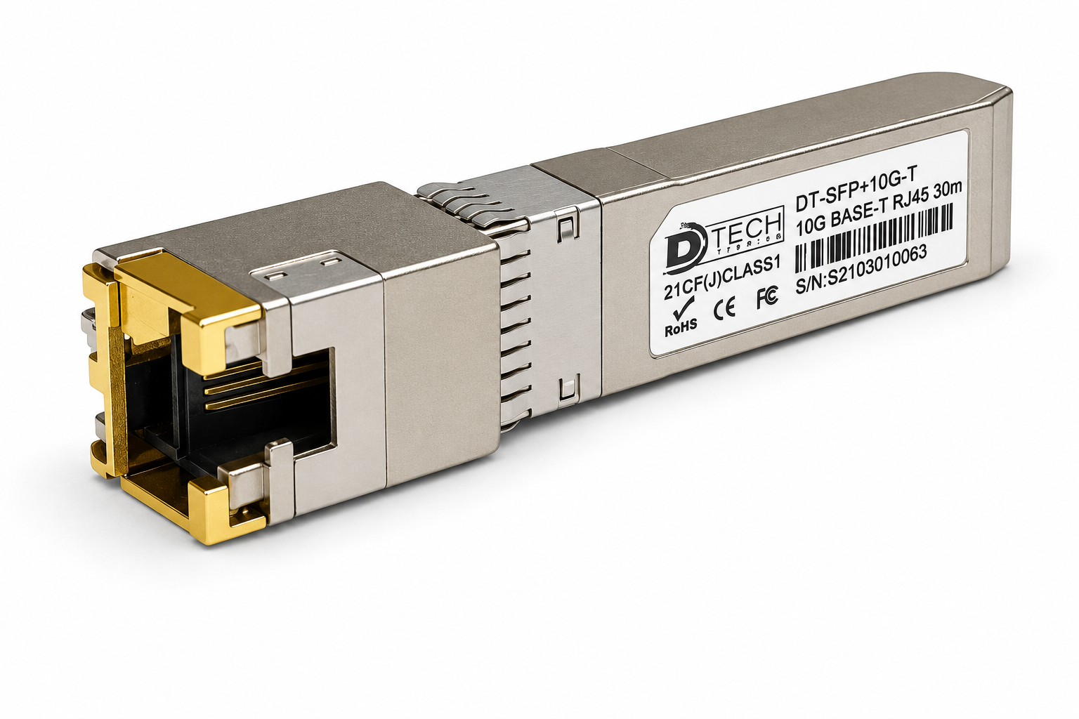
Copper SFP
Rs 7,167
Rs 7,114
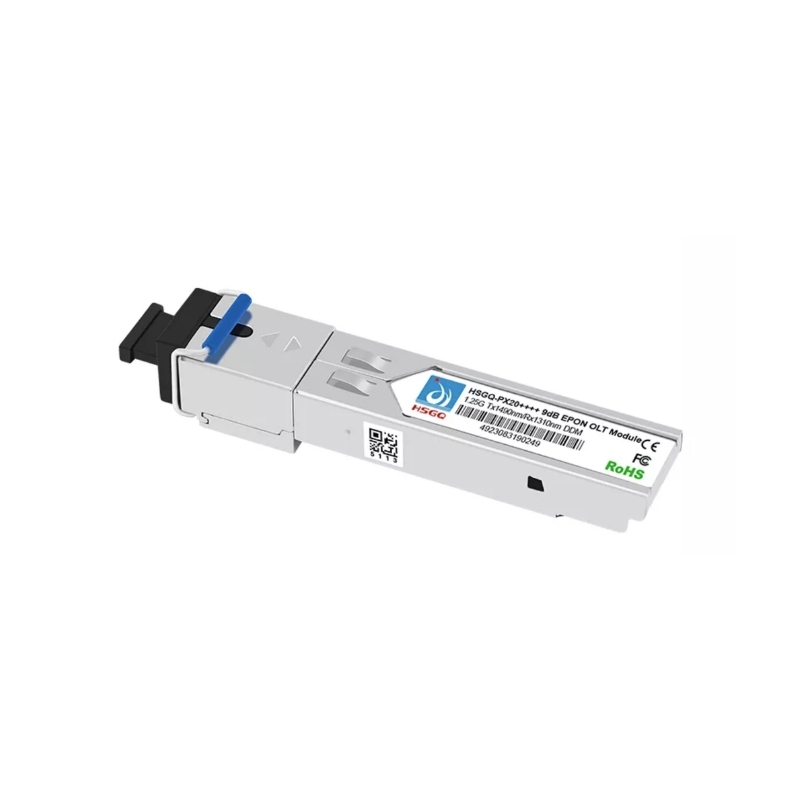
HSGQ EPON SFP
Rs 4,000
Rs 3,800

IP-COM Pro-6-LR
Rs 15,158
Rs 14,575
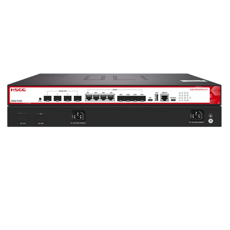
XGSPON OLT - HSGQ
Rs 124,726
Rs 123,247
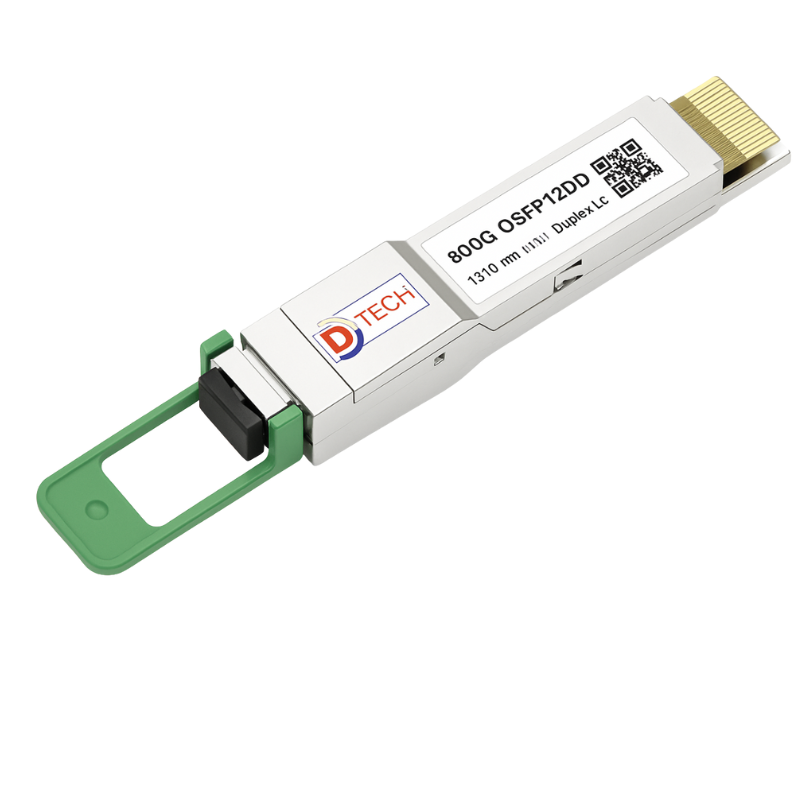
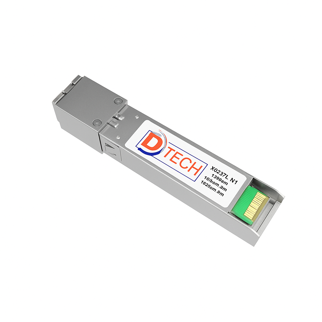
800G OSFP112DD SMF Duplex LC 1310 nm
Contact for price
Multimode 1.25G 850nm
Rs 2,430
Rs 2,412
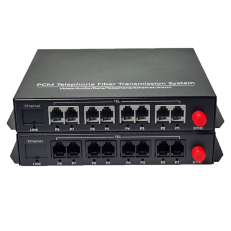
Telephone Converter Converter 8CH
Rs 14,475
Rs 14,304
